
Design FAQs
DESIGN FREQUENTLY ASKED QUESTIONS
If you have have questions about concrete pipe or box culverts, you're in the right spot. If you can't find what you are looking for, though, don't hesitate to reach out and someone from the ACPA will reach out and help find you a solution.

To make concrete pipe more readily available; rather than produce the pipe to the specific D-load required for every job, precast concrete pipe is often specified in terms of a generalized class system. The classes of pipe represent the minimum D-load capacity a pipe produced to that class must have. The classes are designated in ASTM C 76, or AASHTO M 170. The required D-load capacity per pipe is as follows:
| Class | 0.01 inch Crack D-load (lbs/ft/ft) | Ultimate D-load (lbs/ft/ft) |
|
I II III IV V |
800 1000 1350 2000 3000 |
1200 1500 2000 3000 3750 |
The supporting strength of a pipe loaded under three-edge-bearing test conditions expressed in pounds per linear foot of inside diameter or horizontal span.
The complete procedure of the three-edge bearing test and how to calculate the D-Load are explained in ASTM Standard C497, Methods of Testing Concrete Pipe, Concrete Box Sections, Manhole Sections, or Tile.
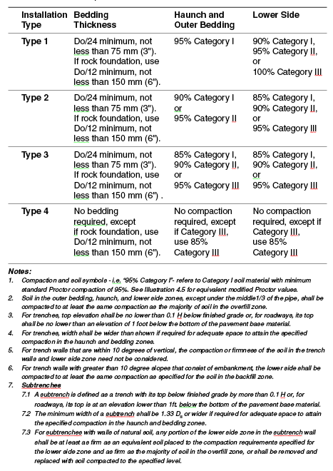
The four Standard Installations provide an optimum range of soil-pipe interaction characteristics. As a designer you can choose from a Type 1 Installation which requires high quality backfill material and compaction levels coupled with a lower strength pipe to a Type 4 Installation which utilizes a lower strength pipe because it was developed for conditions with little or no control over the fill materials or compaction. A Type 1 installation requires greater soil stiffness from the surrounding soils than Type 2, 3, and 4 installations, and is thus harder to achieve. Therefore, field verification of soil properties and compaction levels should be performed.
Soil and Minimum Compaction requirements for each Installation types are referenced shown in various AASHTO and ASTM standards:
The type of Installation required for the project will be based on a combination of factors such as available backfill materials, depth of fill, and required class of pipe. The American Concrete Pipe Association has PipePac software that can be downloaded free of charge. This software will help you analyze different Installation Types to help you decide on the most economical choice.
There are currently two acceptable methods by which concrete pipe may be designed: the Direct Design Method and the Indirect Design Method. The evaluation of the applied loads is similar for both methods, however, evaluation of the pipe’s capacity to resist the applied loads is different with the two methods.
The indirect design method is based on a relationship between the forces that are developed in the pipe wall when the pipe is installed and supported by soil versus the forces developed in the same location of the pipe when tested with the TEB method.
The direct design method follows the conventional design procedure for concrete members where demand versus capacity is determined using load and resistance factors.
Due to advancements in computer technology, the direct design method has become easier to evaluate than it was in the past. However, the indirect method which has been used for approximately 70 years has demonstrated conservatism and is a proven design method.
The minimum fill height requirements for concrete pipes is a function of the load being applied at the surface above the pipe, and the strength of the class of pipe provided.
The fill height of concrete pipes can be reduced to as low as the project requires, provided the pipe is designed to sustain the applied loads. In some cases where extremely heavy machinery will be traveling over the pipe, a concrete pipe with strength above the highest class of pipe denoted in ASTM C76 and AASHTO M170 may need to be utilized. This can be accomplished by working with your local producer. However, in most cases where an AASHTO HL-93 highway load is applied, and the fill height is equal to or greater than 1 foot of cover, a standard Class III pipe or greater will suffice.
For standard HL-93 highway loads, the required D-load at the specified fill height can be found in the ACPA Fill Height Tables. For other design load considerations, ACPA Design Data #1 Highway Live Loads on Concrete Pipe, the ACPA's Concrete Pipe Design Manual, and AREMA Manual for Railway Engineering can be consulted for design assistance.
Concrete Pipe can be installed in either a trench or embankment condition. The type of installation has significant effect on the load carried by the rigid pipe.
- Trench: When concrete pipe is installed in a relatively narrow trench, settlement between the backfill material and the undisturbed soil in which the trench is excavated, generates upward frictional forces. These frictional forces help support the backfill material within the trench, which results in a reduced load on the pipe compared to the weight of the prism of backfill material over the pipe.
- Embankment: In this condition the soil along the pipe wall will settle more than the soil directly above the pipe. This mechanism results in an increased load on the pipe compared to the weight of the prism of the backfill material over the pipe.